Audio Frequency Oscillator
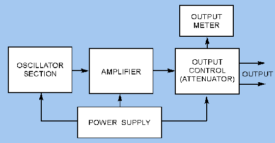
The block diagram of audio frequency oscillator is shown in
the fig. the audio frequency oscillator is designed to provide an output signal
over audio frequency range. The laboratory AFO provides frequency range from 10
Hz to 100 Hz approximately.
Pic 1. Block Diagram Of an Audio Frequency Oscillator
The first block is tunable sinewave oscillator. It is the
heart of the instrument. These oscillators are of the wien bridge or phase
shift type or beat frequency oscillator. This oscillator provides with a
frequency range selector. The output of the sinewave oscillator is applied to
amplifier. The amplifier amplifies the signal generated by the oscillator. The amplifier
also provides buffering between the oscillator and any load connected to the
output terminals.
The amplifier output fed to the attenuation through a switch.
The switch select the sinewave output direct from the output of the amplifier. For
square wave output the amplifier output is connected to square wave shaping
network. The output of wave shaping network is now connected to attenuator. The
attenuator has an amplitude control to get the required output voltage from
audio oscillator.
Separate dial is provided for frequency measurement. Some audio
oscillators use digital frequency counter to display the frequency.

you are clear my mind actually after reading your article i got clear my complete doubt. thanks for such easy understanding post. Sharing on advantages of fet for future aspect at here http://electrotopic.com/what-are-the-advantages-of-fet-over-transistor/
ReplyDeleteGenerate a square wave using AFO of frequency 1KHZ
ReplyDeleteand measure the parameters.